Return to site

Vhdl Code For Serial Adder Using Finite State Machine

broken image


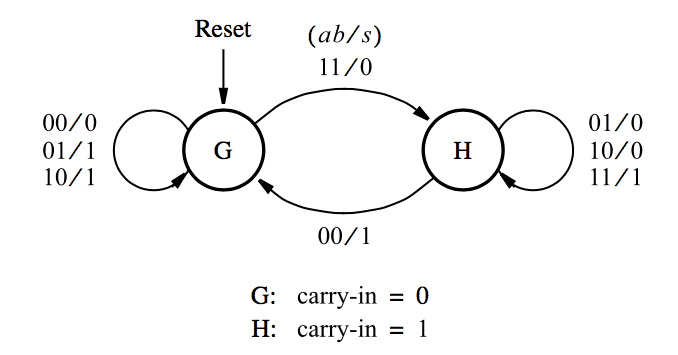
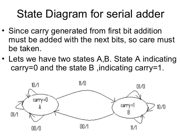
  1. Vhdl Code For Serial Adder Using Finite State Machine Design
  2. Vhdl Code For Serial Adder Using Finite State Machine Diagram

4.2.8 Incomplete VHDL/SystemVerilog Code 76 4.2.9 Overregistered VHDL/SystemVerilog Code 78 4.3 Design Steps Summary 79 5 Regular (Category 1) State Machines 81 5.1 Introduction 81 5.2 Architectures for Regular (Category 1) Machines 82 5.3 Number of Flip-Flops 84 5.4 Examples of Regular (Category 1) Machines 84. A finite-state machine (FSM) or simply a state machine is used to design both computer programs and sequential logic circuits. It is conceived as an abstract machine that can be in one of a finite number of user-defined states. The machine is in only one state at a time; the state it is in at any given time is called the current state. Wall mount for mac. Finite state machines — FPGA designs with VHDL documentation. Finite state machines ¶. In previous chapters, we saw various examples of the combinational circuits and sequential circuits. In combinational circuits, the output depends on the current values of inputs only; whereas in sequential circuits, the output.

This tutorial is about implementing a finite state machine is vhdl. I will go through each and every step of designing a finite state machine and simulating it. Xilinx is used as a tool to construct finite state machine and for simulation and testing purpose. I suppose you know what is finite state machine and why it is used? I will give a short introduction of finite state machines and then move on to the designing phase.
Finite state machine is a graphical model/representation of sequential activities or events. After representing and modeling the events they can be implemented easily in case of sequential logic designs.
Finite state machines can be utilized in many fields of study e.g neural networks, artificial intelligence, mathematics, games, robotics and sequential flow of data. Since we are dealing with the sequential circuits so i will explain their use in sequential circuit design in this tutorial.
There are many fsm(finite state machines) in existence. The two most popular used in digital combinational and sequential circuits are
  • Melay Machine
  • Moore Machine
Vhdl Code For Serial Adder Using Finite State Machine
The main difference between melay and moore is the computation of the next state. In melay machine the output depends on the current state and the input variables. Where as in moore machine the output depends on the current state only. There are also other differences which are hardly highlighted any where.
Vhdl Code For Serial Adder Using Finite State Machine

Moore Machine
  1. More number of states in moore compared to melay for same fsm.
  2. States changes after 1 clock cycle. Latency = 1.
  3. Synchronous output. Because the states are determined in a process.
  4. States are output.

Mealy Machine

  1. Less number of states in mealy compared to moore for same fsm.
  2. State transition on the same clock cycle. Latency = 0.
  3. Asynchronous output.
  4. Transition are output.
In the below figure you can see a melay machine fsm. Fsm has four states S0, S1, S2 and S3. Outputs can be seen on the edges. Inputs are also on the edges. Transitions from one state to another take place on the bases of current state and the inputs. Fsm below is actually a counter. When input is 1 the state moves to next and when the input is 0 state jumps to previous. Counter is 4-bit but only one bit is manipulated in the counter. ‘1' in the 4-bit output moves forward or backward depending on the state and input.
For
The top level entity of melay machine fsm is below. Output is 4-bit named count. Clock and reset are necessary signals for finite state machine. UpDw is a single bit input. When UpDw is 1 state jumps from current to next and when 0 it scroll back to previous state.
Melay machine fsm counter – vhdl top level entity
Output of the melay machine can be seen in the figure below. If you match the behavior of the simulation with the actual state machine above you will find the behavior of the two similar. Which means that the finite state machine is implemented correctly. The simulation below is run on ISim simulator by xilinx.

Vhdl Code For Serial Adder Using Finite State Machine Design

Filed Under: Microcontroller Projects, VHDL
Vhdl code for serial adder using finite state machine calculator
The main difference between melay and moore is the computation of the next state. In melay machine the output depends on the current state and the input variables. Where as in moore machine the output depends on the current state only. There are also other differences which are hardly highlighted any where.

Moore Machine
  1. More number of states in moore compared to melay for same fsm.
  2. States changes after 1 clock cycle. Latency = 1.
  3. Synchronous output. Because the states are determined in a process.
  4. States are output.

Mealy Machine

  1. Less number of states in mealy compared to moore for same fsm.
  2. State transition on the same clock cycle. Latency = 0.
  3. Asynchronous output.
  4. Transition are output.
In the below figure you can see a melay machine fsm. Fsm has four states S0, S1, S2 and S3. Outputs can be seen on the edges. Inputs are also on the edges. Transitions from one state to another take place on the bases of current state and the inputs. Fsm below is actually a counter. When input is 1 the state moves to next and when the input is 0 state jumps to previous. Counter is 4-bit but only one bit is manipulated in the counter. ‘1' in the 4-bit output moves forward or backward depending on the state and input.
The top level entity of melay machine fsm is below. Output is 4-bit named count. Clock and reset are necessary signals for finite state machine. UpDw is a single bit input. When UpDw is 1 state jumps from current to next and when 0 it scroll back to previous state.
Melay machine fsm counter – vhdl top level entity
Output of the melay machine can be seen in the figure below. If you match the behavior of the simulation with the actual state machine above you will find the behavior of the two similar. Which means that the finite state machine is implemented correctly. The simulation below is run on ISim simulator by xilinx.

Vhdl Code For Serial Adder Using Finite State Machine Design

Filed Under: Microcontroller Projects, VHDL

Vhdl Code For Serial Adder Using Finite State Machine Diagram


broken image